

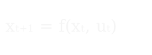



Putting NMPC trajectory tracking on a real quadcopter
2025 / Hardware and integration, with Desmond Fotock / ROS 2 + PX4 + MAVLink + Raspberry Pi + NMPC + 3D Printing
TLDR
Collaborative project with my friend Desmond. He leads the NMPC controller; my piece is making the drone fly: the hardware build, wiring, sensor mounting, and the ROS 2 bridge between the PX4 autopilot and the Raspberry Pi companion computer. We're seeing how far we can close the sim-to-real gap on NMPC and other control concepts we found interesting.
What the project is

An F450 quadcopter that follows a desired 3D trajectory using nonlinear model-predictive control. The controller looks ahead over a short horizon and picks rotor thrusts that keep the airframe on the trajectory inside actuator and stability limits. Right now everything runs in Gazebo SITL against PX4. Solves stay under a millisecond and position error sits around 12cm. Hardware flight testing comes next. After that, we're curious about how ML and NMPC could work together inside one loop.
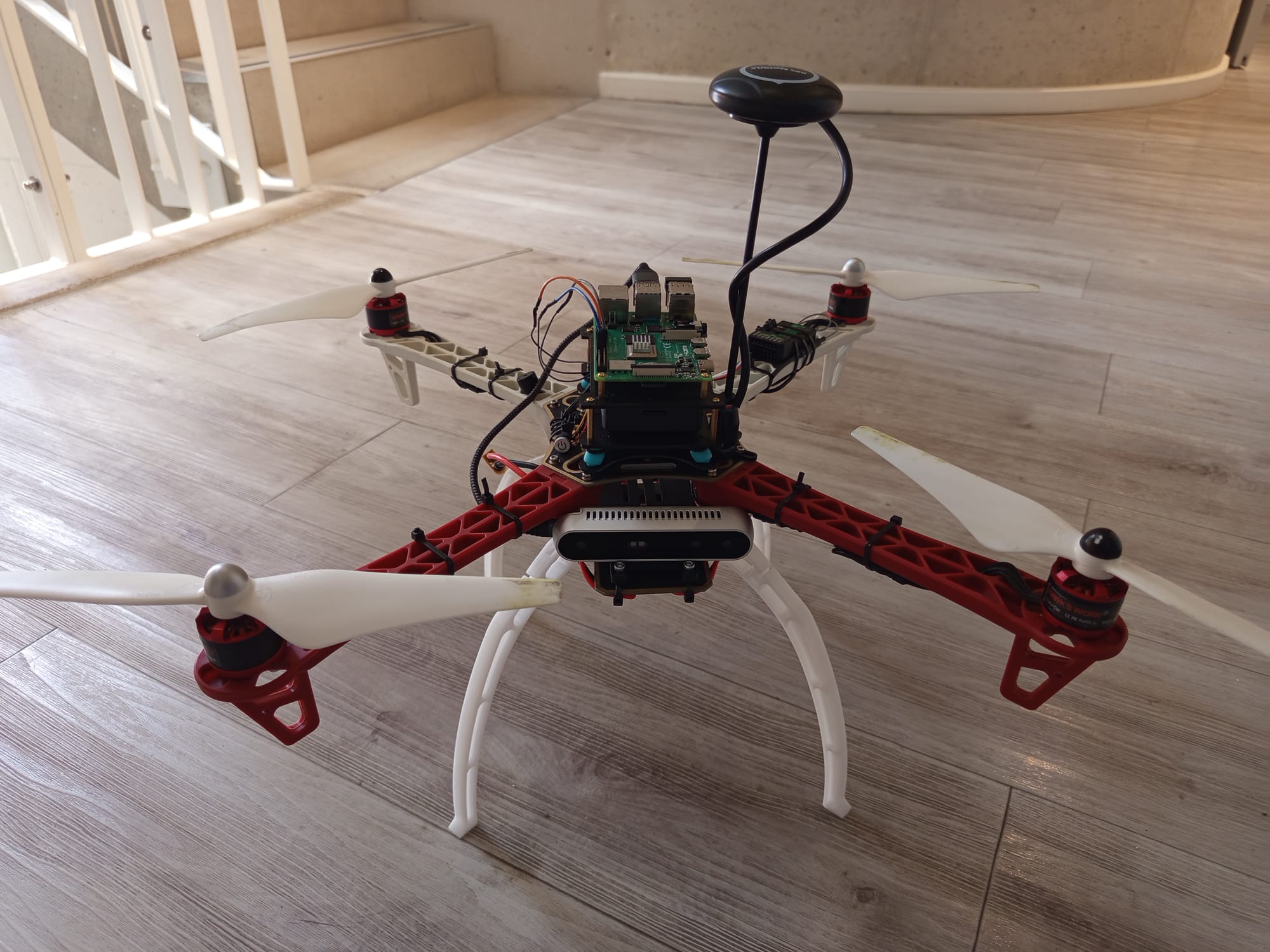
The assembled F450, with the Pixhawk, Pi, and GPS stack on the airframe.
That description is harder than it sounds. Quadcopters are unforgiving. They fly because four motors balance against gravity. Get the inner-loop attitude wrong and they fall out of the sky. Get the timing between the high-level controller and the flight stack wrong and the same thing happens, slower.
The two halves of making this fly
Desmond owns the controller — the formulation, the model, the cost function, the solver, the simulation work. I own the integration: the hardware build, the wiring, the ROS 2 bridge to PX4, and the project's documentation. We go back and forth on ideas in both directions: I flag formulation choices that'll be hard to land on real hardware, and he flags integration decisions that would over-constrain the controller.
Hardware build
I sourced and assembled the airframe: an F450 frame with four EMAX motors and ESCs, a Pixhawk autopilot, a Raspberry Pi 4B companion computer, a GPS module, and an Intel RealSense depth camera. Fitting all of that on one frame cleanly is its own design problem.
The layout I landed on puts every component on its own custom 3D-printed plate. Cabling stays tidy, mass distribution stays balanced, and nothing floats loose.
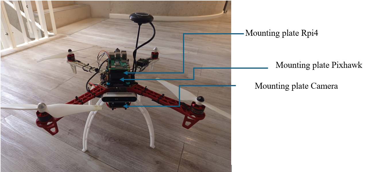
Three plates carry the Pi, the Pixhawk, and the camera.
The Pi + Pixhawk plate is the busiest of the three — designed against the F450's frame holes, printed, then mounted.
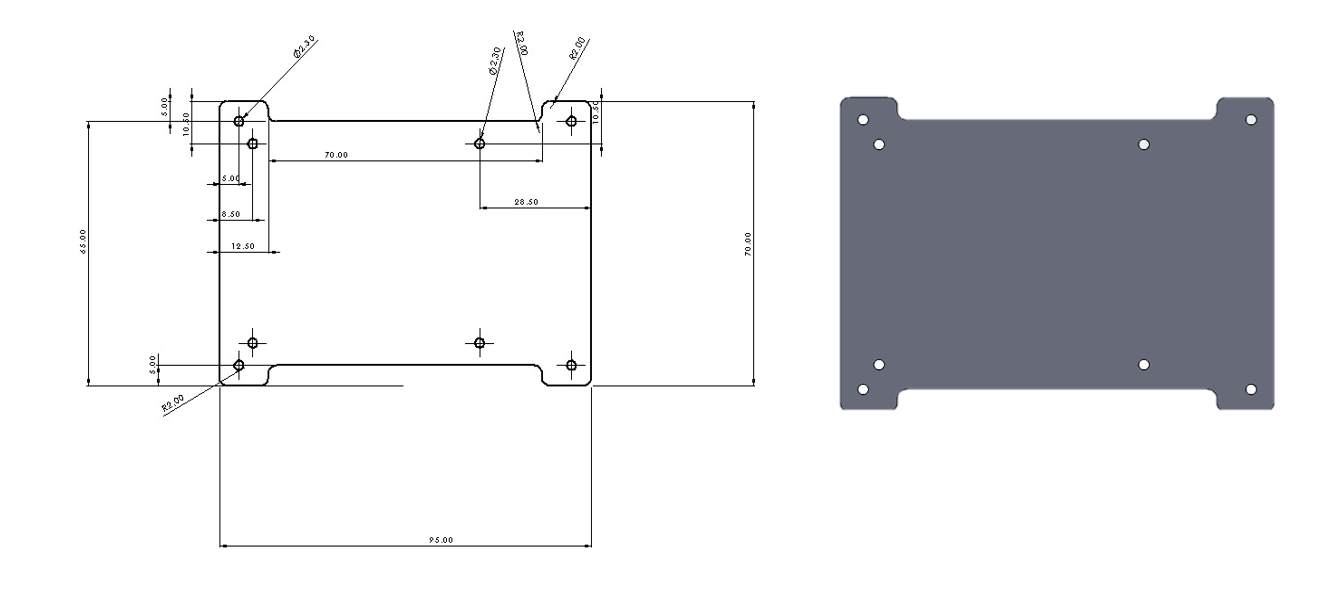
The Pi + Pixhawk plate, from dimensioned drawing to 3D render.
I designed and wired the power tree off a single battery: the PDB fans out to four ESCs (and the motors they drive), a 5V DC-DC converter to the Pi (which feeds the RealSense it carries), and the Pixhawk, with the GPS and receiver downstream.
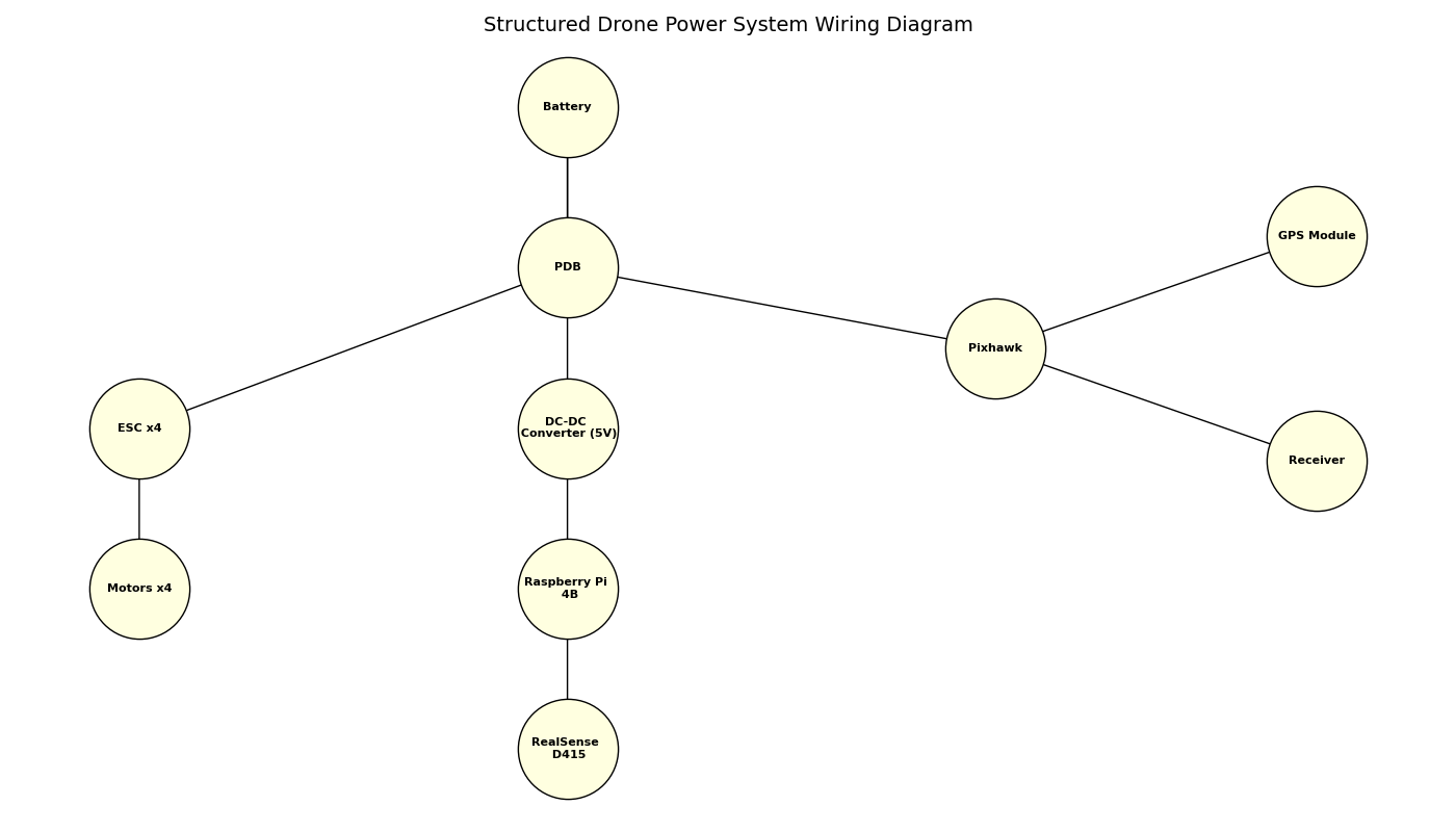
Battery → PDB → ESCs and motors / 5V DC-DC → Pi → RealSense. Pixhawk hangs off the PDB, with GPS and receiver downstream.
Wiring the controller to the flight stack
PX4 is the flight controller firmware. It runs the inner control loops (attitude, rate, motor mixing) at high rate on a dedicated microcontroller, and expects to be commanded from outside through MAVLink's offboard control mode. An NMPC has to run on a companion computer and command PX4 across that interface.
On this build, the NMPC runs on the Raspberry Pi on the airframe, alongside the state-estimation pipeline and the ROS 2 nodes that feed it. A ROS 2 / MAVLink bridge connects the two. Everything currently runs in Gazebo SITL against PX4; hardware flight testing comes next.
Concepts worth taking away
A few things from this project that have transferred to the work I've done since:
- PX4 + companion computer is a transferable pattern, not a one-off setup. It cleanly separates the inner-loop control (which needs to be deterministic and run on dedicated hardware) from the high-level control (which can be heavier and run on a general-purpose computer). The same pattern shows up in ground robots, drones, and rovers. Once you've internalised it, every "where should this code run" question gets easier.
- Closing the sim-to-real gap is its own engineering problem. Most NMPC results come out of controlled environments: motion capture rigs, indoor cages, clean state estimates. The harder problem is making those same concepts hold up in the elements, with wind, sensor noise, and imperfect state.
- Bring the integration view into the controller design loop early. A controller designed in isolation will solve the problem on paper. Having someone asking "what's the rate, what's the delay, what does the autopilot accept" while the formulation is still in flight catches a lot of mismatches before they become flight-test failures.
Technologies and patterns
PX4 (autopilot firmware) · MAVLink (autopilot ↔ companion bridge) · ROS 2 (companion-side message bus and node framework) · Raspberry Pi (companion computer) · airframe assembly and wiring
Photos and diagrams above are from the project repo and wiki, joint work with Desmond Fotock.